Semi-finishedproduct : No
Data Record : No
High-concerned chemical : none
Electronic : No
Size : Backfeed Protection
Type : Ideal Diode Module
Model Number : Idea Diode
DIY Supplies : Electrical
Brand Name : Aideepen
Style : Rectifier
Output Voltage : DC 4-90V
Origin : Mainland China
Certification : CE
DC 3.5-60V 4-90V 20A Ideal Diode Rectifier Module Ultra Low Drop Anti-reverse Current Anti-backflow Protection With Heat Sink
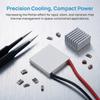
20A
Features
1. Supports DC 4-90V input, suitable for a wide range of solar and battery systems
2. Extremely low voltage drop, effectively prevents reverse leakage from batteries and improves efficiency
3. Simple wiring; can replace traditional reverse-connection protection diodes
4. Built-in heat sink effectively reduces heat generation
5. Backflow and reverse-connection protection safeguards the circuit against reverse current damage
Parameter
Operating Voltage Range: 60V: DC 3.5–60V / 90V: DC 4–90V
Operating Current: 20A (Enhance heat dissipation for currents exceeding 15A)
Quiescent Current: 300μA
On-Resistance: 60V: 4.6mΩ / 90V: 3.6mΩ
On-state voltage drop: Actual operating current × on-state resistance; for example, at 10A, voltage drop = 10 × 0.0036 = 0.046V
On-state power dissipation: (Actual operating current)² × on-state resistance; for example, at 10A, power dissipation = 10 × 10 × 0.0046 = 0.36W
Switching frequency: Within 150 Hz
Reverse polarity protection: Yes, will not burn out if connected in reverse
Operating temperature: -40 to +125°C
Applications
1. Dual-power-supply parallel configuration, UPS applications.
2. Redundant power supply applications.
3. Master/slave battery parallel connection.
4. Uninterrupted battery replacement for drones, electronic devices, etc.
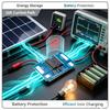
5. Backfeed protection for batteries, solar systems, and power modules.
6. Reverse polarity protection for DC electronics, power modules, and electronic devices.
Precautions
1. The negative terminal of the main current circuit does not need to pass through the module, but the negative terminal on the module must be connected (a thin wire may be used).
2. This module is for DC applications only, with a switching frequency not exceeding 150 Hz; it cannot be used for AC rectification.
3. Beware of surge voltages causing chip breakdown. For high operating voltages or inductive loads, install TVS diodes and electrolytic capacitors at the input and output to absorb surge voltages.
4. When operating currents are high and heat generation is significant, enhance heat dissipation (by using larger heat sinks or forced air cooling).
5. Multiple modules can be connected in parallel to increase current capacity or to expand the number of channels.
6. When using a primary/secondary battery in parallel, if the primary battery does not have an ideal diode connected, ensure that the secondary battery voltage does not exceed the primary battery voltage. If both the primary and secondary batteries have ideal diodes connected, there is no voltage difference requirement when connected in parallel.
7. Do not use the diode or resistance ranges on a multimeter to measure the internal resistance of an ideal diode; this is an incorrect measurement method. The internal resistance can be calculated based on the voltage drop across the ideal diode and the current flowing through it. For example: If the current flowing through the diode is 10A and the voltage drop is 0.015V, the internal resistance is 0.015V / 10A = 0.0015 ohms. Note that the effect of line voltage drop must be taken into account.
50A/70A
Product Features
1. Free choice of 50A/70A high current for stronger load-bearing capacity
2. DC 4-90V wide voltage, suitable for multiple scenarios
3. Low voltage drop to prevent backflow and protect against overheating
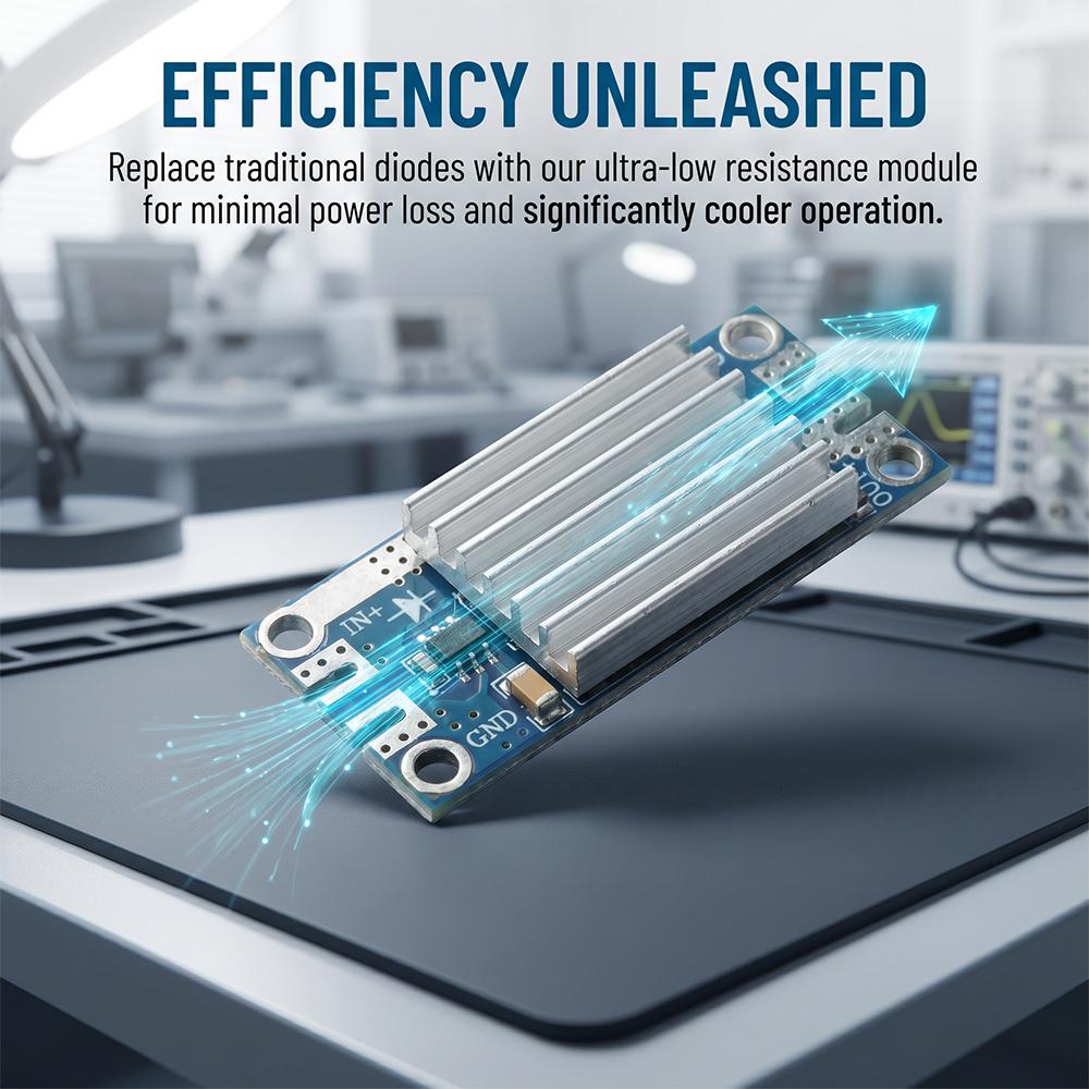
4. Replace traditional diodes with high efficiency and low losses
5. Solar specific rectification for more stable charging
Product parameters
Input voltage: DC 4-90V
Working current: 50A/70A (if it exceeds 20A/30A, please strengthen heat dissipation)
Static working current: 300uA
Internal resistance during conduction: 50A: 1.5m Ω/70A: 0.75m Ω
Conduction voltage drop: actual working current * conduction internal resistance, for example, when 10A, voltage drop=10 * 0.0036=0.046V
Power loss during conduction: square of actual operating current * conduction resistance
Open frequency: within 150HZ
Reverse input protection: Yes, reverse connection does not burn
Working temperature: -40~+125 ° C
Scope of application
1. Dual power parallel supply and UPS application.
2. Redundant power supply application.
3. Parallel connection of primary/secondary batteries.
4. Drones, electronic devices, etc. are constantly powered to replace batteries.
5. Anti backflow of batteries, solar energy, and power modules.
6. DC electronic and power modules, electronic equipment input reverse protection.
Precautions
1. The negative pole of the main current circuit does not need to pass through the module, but the negative pole on the module must be connected (using a thin wire).
2. It can only be used in DC, with a turn-on frequency not exceeding 150HZ, and cannot be used for AC rectification.
3. Pay attention to the breakdown of the chip by surge voltage. If the working voltage is high and there are inductive loads, please increase the input and output
TVS diodes and electrolytic capacitors absorb surge voltages.
4. When the working current is high and the heat generation is significant, it is necessary to strengthen heat dissipation (by increasing the number of heat sinks or air cooling).
5. Multiple parallel connections can be used to increase current, or multiple parallel connections can be used to increase the number of channels.
6. When applying the main/auxiliary battery in parallel, if the main battery is not equipped with an ideal diode, attention should be paid to the voltage of the auxiliary battery
Cannot exceed the voltage of the main battery. If both the main and auxiliary batteries are connected to ideal diodes, there is no voltage when connected in parallel
Poor requirements.
7. Do not measure the internal resistance of an ideal diode using the diode and resistance settings of a multimeter, as this is an incorrect measurement
Method: The internal resistance can be calculated by the voltage drop of an ideal diode and the current passing through it. For example, the current passing through is 10A, with a voltage drop of 0.015V and an internal resistance of 0.015V/10A=0.0015 ohms. Attention should be paid to the impact of voltage drop on the circuit.
Package include
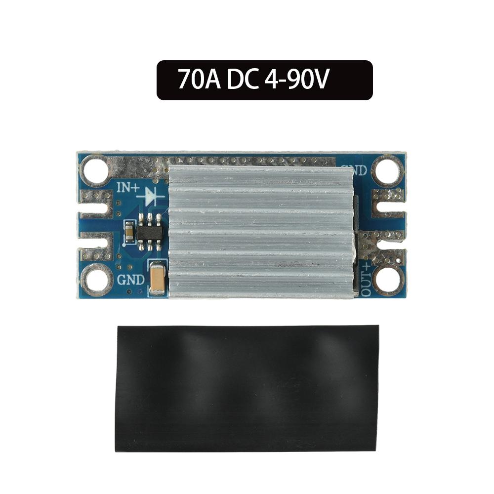
Diode module *1 (model of your choice)
Heat-shrink tubing *1
label:yes




 Возврат по недоставке