Quantity : 1
High-concerned chemical : none
Package : TQFP
is_d : Yes
Supply Voltage : As Description
Application : Electric Toy
Type : Module
Brand Name : DIY NOW
Origin : Mainland China
Condition : New
Operating Temperature : As Description
Condition : New
Type : DIY Welding Kit
Key Word : Electronic Component Kit
Dropship : Support
DIY Welding Kit Simulates Electronic Candle Lighting And Blow Control Simulation Teaching Welder Practice Circuit Board
Features:
1. Simulates ignition and extinguishing, offering a fun and interactive experience.
2. Blow-out extinguishing is achieved through a microphone sensing airflow.
3. Sensitivity adjustment to accommodate diverse usage environments.
4. 5V DC power supply, safe and stable, suitable for a variety of scenarios.
5. Compact circuit board, easy to assemble, perfect for DIY enthusiasts.
Operating Principle:
This electronic candle circuit utilizes one D flip-flop from the CD4013 dual D flip-flop, wired as an RS flip-flop. When powered on, the differential circuit formed by C3 and R7 generates a high-level differential pulse to the IRD terminal of U1, forcing the circuit to reset. The IRD terminal outputs a low level, which is fed to the base of transistor Q4, turning Q4 off and turning off the LED. When a lighter is placed near infrared receiver diode HW, it enters reverse breakdown conduction, its resistance suddenly decreasing. The base of Q1 goes low, turning on transistor Q1. The high-level pulse generated at its collector is sent to U1's ISD terminal, causing 1Q to go high. This pulse is then fed through resistor R8 to the base of Q4, turning on Q4 and illuminating the LED. This process is similar to lighting a candle with a lighter. Even if the lighter is removed from the infrared receiver, the circuit remains lit. When blowing into the electret microphone MIC, the audio signal from the microphone is amplified by C2 and fed to Q2. This amplified signal turns on Q3, generating a high-level differential pulse at U1's 1RD terminal. This resets the trigger, causing 1Q to go low, turning off Q4, and turning off the LED, creating the effect of a candle being extinguished by wind. Potentiometer R3 can be used to adjust the light intensity sensitivity.
Product Parameters:
Kit Name: Simulated Electronic Candle
Power Supply: DC 5V
PCB Size: 45*30mm
Board Function: Simulates lighting and blowing out candles, creating a fun and engaging experience, while also realizing the functions of an electronic candle.
Functional Description: This simulates an electronic candle, achieving the effect of "igniting with a match and extinguishing with a breeze." The design is inspired by real-life scenarios. After modification, the circuit can be used for birthday parties.
Soldering Instructions:
1. Ensure the resistance of each resistor matches the resistance value marked on the board.
2. Ensure the capacitance of each capacitor matches the resistance value marked on the board.
3. Transistors come in 9012 and 9013 sizes; carefully check the model number before soldering.
4. The black infrared receiver and transparent LED both have the long positive lead.
5. The direction of the chip notch and the base notch must match the notch marked on the board. 6. Insert the microphone according to the shape on the board, covering the marking circle, or the pin connected to the outer casing should be the negative terminal.
7. The power supply voltage must be 5.0V DC. Pay attention to the positive and negative poles.
8. Check for short circuits and poor solder joints before reapplying power.
9. Test in a dark environment or in a bright environment with the infrared receiver. This is equivalent to keeping the ignition on and the light on continuously.
Product List:
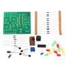
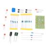
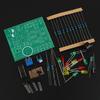
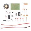
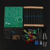
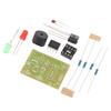
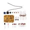
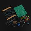
1x DIY Electronic Candle Parts
label:yes


 Возврат по недоставке