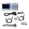
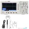
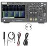
Feature
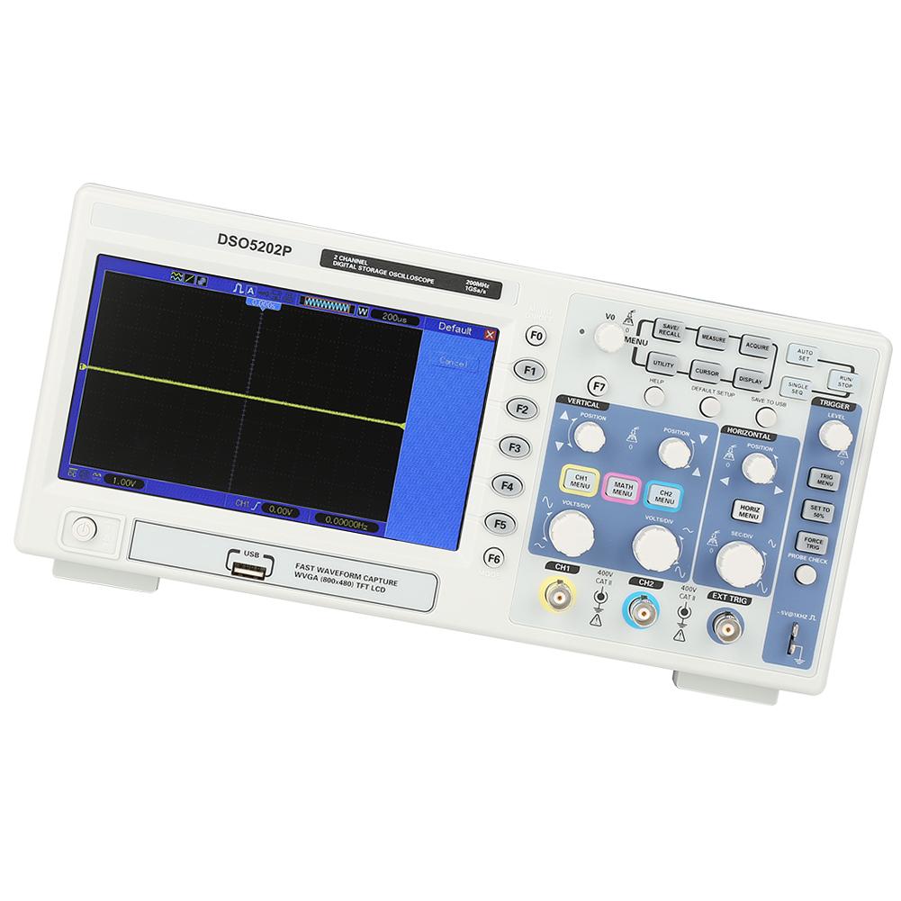
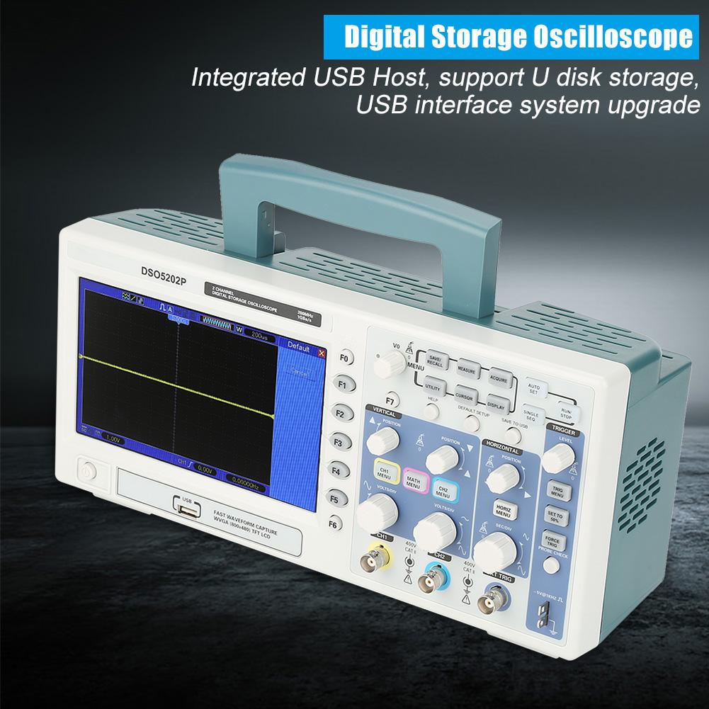
With bandwidth of 200MHz and real time sampling rate of 1GSa s, more than 1000 waveforms and other information can be stored
Large and clear screen (7.0 inch LCD, 800x480 resolution), humanized operation interface,Powerful trigger function
Integrated USB Host, support U disk storage, USB interface system upgrade
The 7 inch 64K TFT real color LCD display is clear and lifelike
Ultra thin design, compact size, easy to carry
Specification:
Brand
Hantek
Model
DSO5202P
Voltage
110 240V
Plug
EU plug
Acquisition
Sample Rate
Real Time Sample: 1GS s
Acquisition Modes
Normal
Normal data only
Peak Detect
High frequency and randon glith capture
Average
Wavefom Average, selectable 4,8,16,32,64,128
Inputs
Inputs Coupling
AC, DC, GND
Inputs Impendance
1M Ohm + 2percent I 20pF+ 3pF
Probe Attenuation
1X, 10X
Supported Probe Attenuation Factor
1X, 10X, 100X, 1000X
Maximum Input Voltage
CAT I and CAT II: 300VRMS (10x), Installation Category;
CAT III: 150VRMS (1x);
Installation
Category II: derate at 20dB decade above 100kHz to 13V peak AC at 3MHz*
and above. For non sinusoidal waveforms, peak value must be less than
450V. Excursion above 300V should be of less than 100ms duration. RMS
signal level including all DC components removed through AC coupling
must be limited to 300V. If these values are exceeded, damage to the
oscilloscope may occur.
Horizontal System
Sample Rate Range
500MS s 1GS s
Waveform Interpolation
(sin x) x
Record Length
40K
SEC DIV Range
2ns div to 40s div
Sample Rate and
Delay Time Accuracy
+ 50ppm(at over any more than 1ms time interval)
Position Range
2ns div to 10ns div; ( 4div x s div) to 20ms;
Delta Time Measurement Accuracy
(Full Bandwidth)
Single shot, Normal mode:+ (1 sample interval +100ppm x reading + 0.6ns);
>16 averages:+ (1 sample interval + 100ppm x reading + 0.4ns);
Sample interval = (s div) 200
Vertical System
Vertical Resolution
8 bit resolution, all channel sampled simultaneously
Position Range
2mV div to 10V div
Bandwidth
200MHz
Rise Time at BNC( typical)
1.8ns
Analog Bandwidth in Normal and Average modes at BNC or with probe, DC Coupled
2mV div to 20mV div, + 400mV; 50mV div to 200mV div, + 2V
500mV div to 2V div, + 40V; 5V div, + 50V
Math
+, , x, , FFT
FFT
Windows: Hanning, Flatop, Rectamgular, Bartlett, Blackman;
1024 sample point
Bandwidth Limit
20MHz
Low Frequency Response ( 3db)
less than 10Hz at BNC
DC Gain Accuracy
+ 3percent for Normal or Average acquisition mode, 5V div to 10mV div;
+ 4percent for Normal or Average acquisition mode, 5mV div to 2mV div
DC Measurement Accuracy,
Average Acquisition Mode
When vertical displacement is zero, and N more than 16:+ (3percent x reading + 0.1div + 1mV) only 10mV div or greater is selected;
When
vertical displacement is not zero, and N more than 16: + (3percent x (reading +
vertical position) + 1percent of vertical position + 0.2div); Add 2mV for
settings from 2mV div to 200mV div; add 50mV for settings from 200mV div
to 5V div
Volts Measurement Repeatability,
Average Acquisition Mode
Delta volts between any two averages of more than 16 waveforms acquired under same setup and ambient conditions
Trigger System
Trigger Types
Edge, Video, Pulse, Slope, Over time, Alternative
Trigger Source
CH1, CH2, EXT, EXT 5, AC Line
Trigger Modes
Auto, Normal, Single
Coupling Type
DC, AC, Noise Reject, HF Reject, LF Reject
Trigger Sensitivity
(Edge Trigger Type)
DC(CH1,CH2):
1div from DC to 10MHz; 1.5div from 10MHz to 100MHz; 2div from 100MHz to Full;
DC(EXT):
200mV from DC to 100MHz; 350mV from 100MHz to 200MHz;
DC(EXT 5):
1V from DC to 100MHz;1.75V from 100MHz to 200MHz;
AC: Attenuates signals below 10Hz;
HF Reject: Attenuates signals above 80kHz
LF Reject: Same as the DC coupled limits for frequencies above 150kHz; attenuates signals below 150kHz
Trigger Level Range
CH1 CH2: + 8 divisions from center of screen;
EXT: + 1.2V;
EXT 5:+ 6V
Trigger Level Accuracy( typical)Accuracy is for signals having rise and fall times more than 20ns
CH1 CH2: 0.2div x volts div within + 4 divisions from center of screen;
EXT: + (6percent of setting + 40mV);
EXT 5: + (6percent of setting + 200mV);
Set Level to 50percent (typical)
Operates with input signals more than 50Hz
Video Trigger
Video Trigger Type
CH1, CH2: Peak to peak amplitude of 2 divisions;
EXT: 400mV;
EXT 5: 2V
Signal Formats and Field Rates, Video Trigger Type
Supports NTSC, PAL and SECAM broadcast systems for any field or any line
Holdoff Range
100ns 10s
Pulse Width Trigger
Pulse Width Trigger Mode
Trigger when (< , >, = , or not=); Positive pulse or Negative pulse
Pulse Width Trigger Point
Equal: The oscilloscope triggers when the trailing edge of the pulse crosses the trigger level.
Not
Equal: If the pulse is narrower than the specified width, the trigger
point is the trailing edge. Otherwise, the oscilloscope triggers when a
pulse continues longer than the time specified as the Pulse Width.
Less than: The trigger point is the trailing edge.
Size
32*14*11.5cm 12.6*5.5*4.5in
Weight
Approx.2868g 101.2oz
Package list:
1 x DSO5202P Oscilloscope
2 x test probe
1 x USB cable
1 x CD
1 x Power cable
1 x adjust tool
1 x locating sleeve
6 x marking ring
Note: Please kindly make a note if you need any adapter.




 Возврат по недоставке