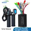
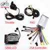
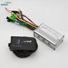
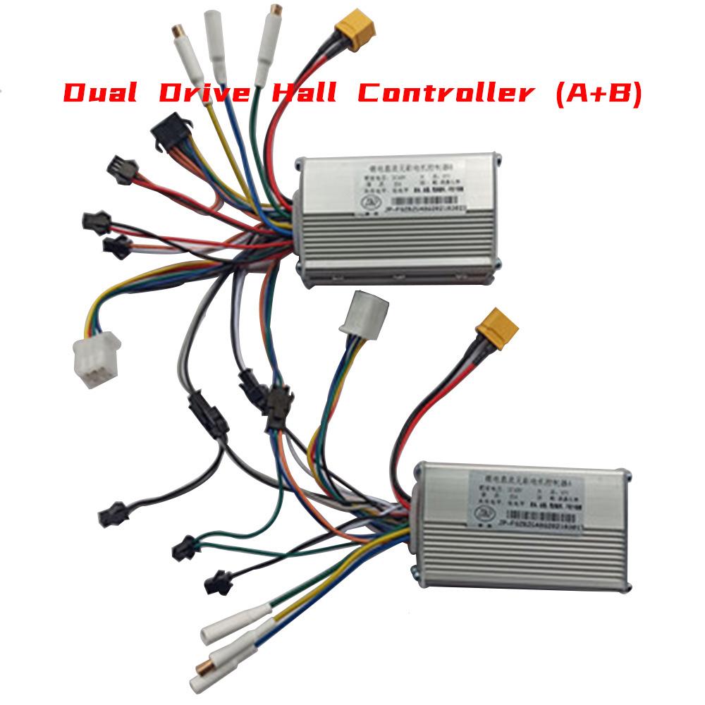
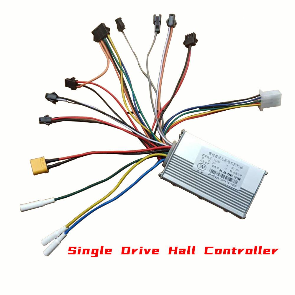
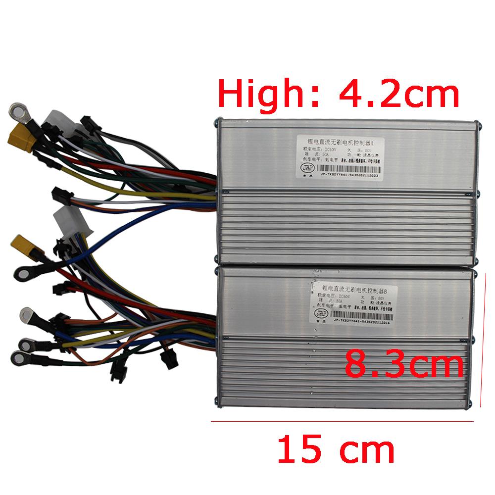
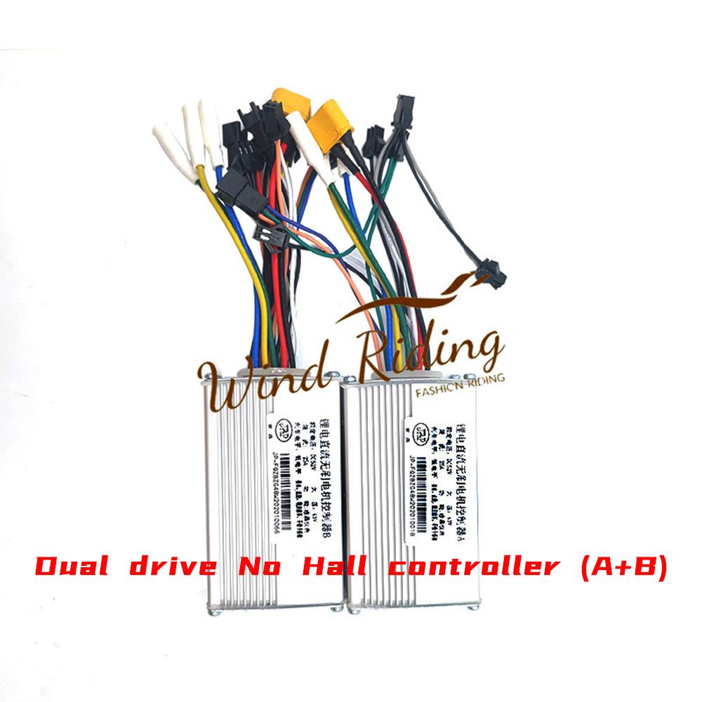
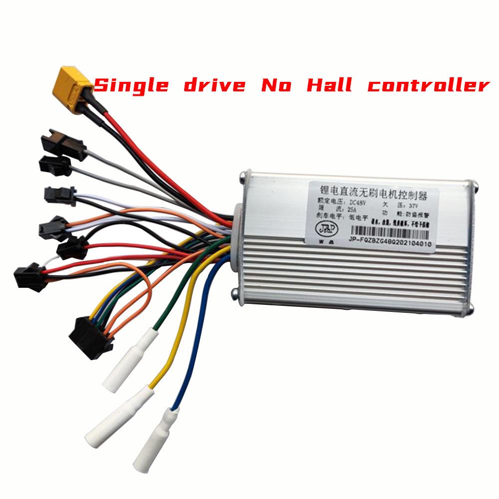
1. The controller is divided into two styles: single drive and double drive (A+B).
Hall/No Hall (Differentiation)
a. The rear wheel motor only has 3 thick phase wires, which means no Hall
motor
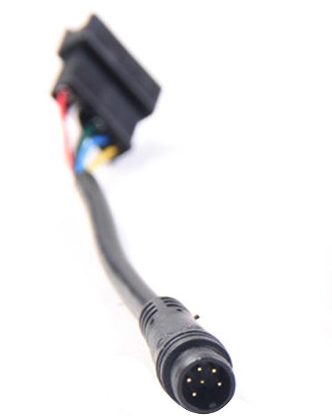
b. In addition to the 3 phase wires, there is another bundle of wires (the above are 5 thin wires) which is the Hall motor
2.
Single drive: 36v 16a no hall (anti-theft), 36v19a no hall (anti-theft), 48v25a no hall (anti-theft), 48v25a no hall (anti-theft), 52v25a no hall (anti-theft), 52v25a no hall (anti-theft)
Dual drive: 48v25a Hall (A+B) (anti-theft), 52v25a Hall (A+B) (no anti-theft), 52v25a no Hall (A+B) (no anti-theft), 60v25a Hall (A+B) (anti-theft), 60v25a Hall (A+B) (anti-theft), 60V50a Hall (anti-theft)
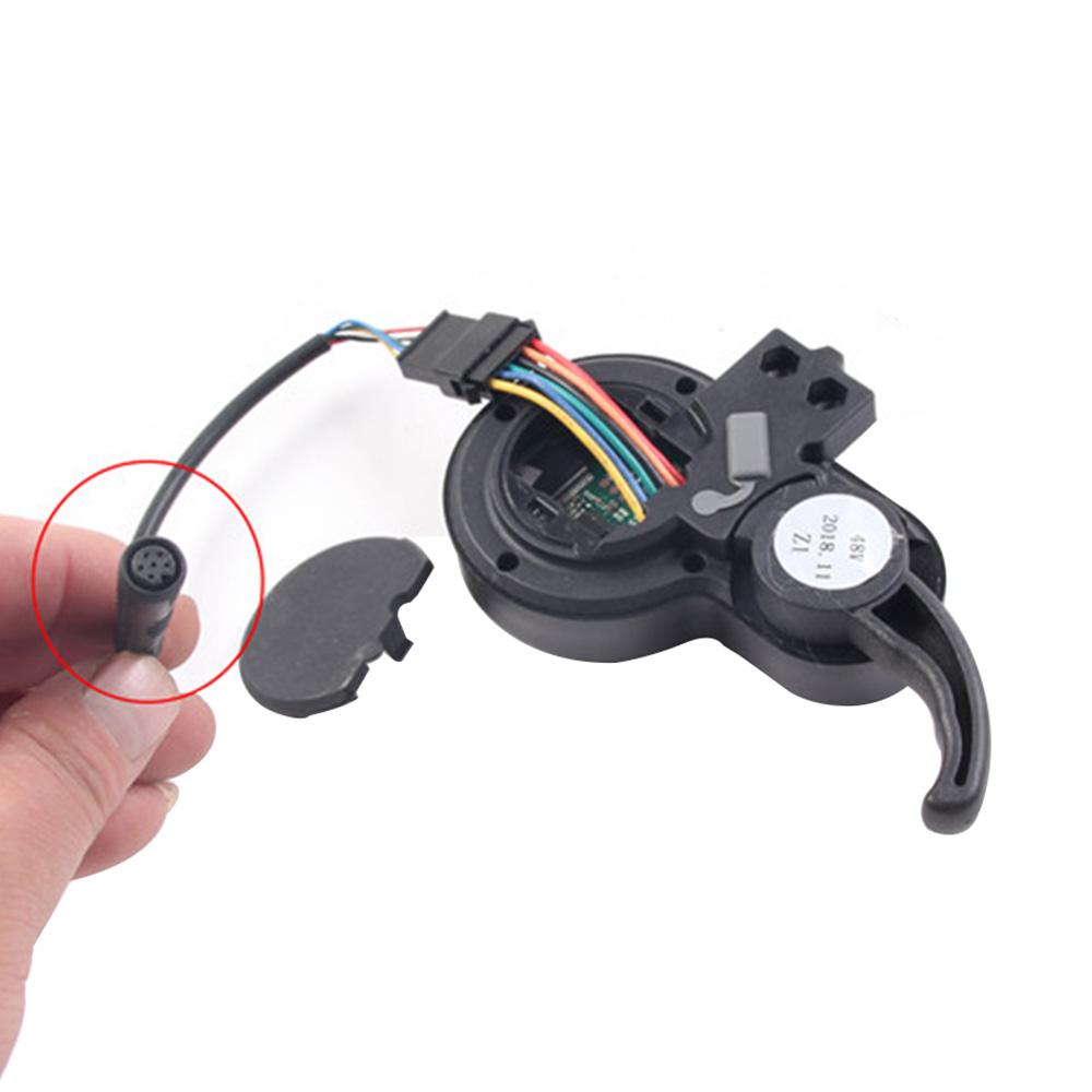
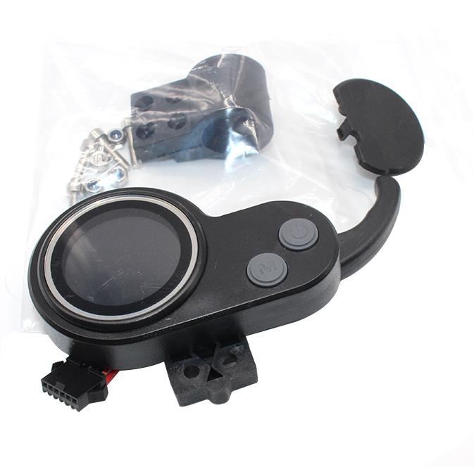
The throttle instrument is now a new color screen, which is the same as the old blue screen of Jipin.
The new 36v 48v 52v 60v is universal, the factory setting is usually 36v
Set the undervoltage "P1" (not setting the data display will be inaccurate, but it will not affect the use)
3. About installation:
The controller is [J&P] brand, other brands of controllers are not recommended to buy
(Different brands generally have communication protocols, which do not necessarily match. It is recommended that the instrument and the controller be replaced together)
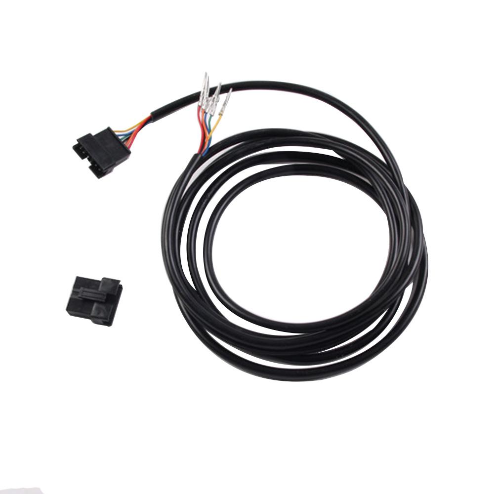
Different batches of goods sometimes have slightly different connectors, but the main lines and basic functions have all the basic functions. Jipin brand controller Hall line is generally fine without plugging in. Anti-theft means that there is an alarm connector installed on the controller. We all have 3 wire connectors, usually red, black and orange, red, orange and black. If the alarm is not connected, you can short this connector (the red and orange wires can be connected), and the alarm connector A meter that is not short-circuited cannot be turned on.
When you receive the goods, you can first connect the 3 wires of the instrument, power supply and motor
Normal situation: The wheels can be turned when the meter is turned on, and then compare the rest of the lines with our wiring diagram to find the line corresponding to your car and connect it.
Note: Friends who do not understand circuit and electronic knowledge, please try not to install it by yourself!
Do not connect the wrong positive and negative when wiring, or the accessories will be burned in severe cases!
Water enters, the controller is damaged or the label is torn off due to man-made modifications, and the casing is opened privately (not for sale)
About installation:
Precautions
1. Cut off the power supply before wiring, and connect each wire as shown in the wiring diagram.
2. The controller should be installed in ventilated, waterproof and shockproof parts.
3. The connector of the controller should be inserted in place, and it is forbidden to reversely connect the positive and negative poles of the controller power supply.
1. Connect the positive and negative poles of the power supply and the switch wire. The thick red wire is the positive pole of the power supply, the thick black wire is the negative pole of the power supply, and the thin orange wire is the electric door lock. The positive and negative poles must be connected correctly.
2. Connect the motor phase line, motor phase (u, v, w output)
The thick yellow line is U, the thick green line is V, and the thick blue line is W.
The phase wires must be connected in place! (Otherwise the motor will have various problems)
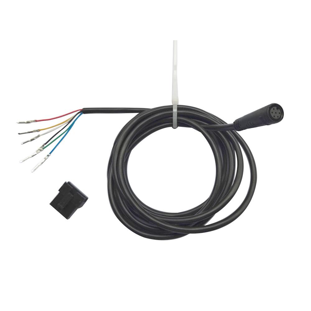
3. Connect the Hall wire, the thin red wire is the +5V power supply, the thin black wire is the ground wire, (note that the +5V power supply and the black ground wire must be connected correctly) The thin yellow wire is A, the thin green wire is B, and the thin blue wire The color line is C.
After completing the first, second and third steps, you can test the machine first, confirm the positive and negative poles again, turn on the power after it is completely correct, turn on the electric door lock, and plug the learning line, whether the motor rotates, whether the rotation direction is correct, the motor is reversed and re-plugged to learn After the motor turns correctly, disconnect the learning line (after power-on, the debugging line is allowed to learn within 2 minutes).
Fourth, connect the handle, thin red wire +5V power supply, thin green (or thin white) signal input, thin black wire ground wire. Note that the +5V power supply and the black ground wire must be connected correctly.
5. Connect other functional lines, carefully identify the positive and negative poles and do not connect them in reverse, such as connecting high/low brake lines, power assist, cruise, third gear, anti-theft alarm, reversing, speed limit, etc.
Model Number: JIPIN
Brand Name: NONE
Origin: Mainland China
Voltage: 48V
is_customized: Yes






 Возврат по недоставке