<kse:widget data-widget-type="customText" id="1005000003571620" type="relation"></kse:widget>
I.The main technical parameters:
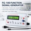
1. Output waveforms: sine wave, square wave, triangle wave, forward sawtooth wave, reverse sawtooth wave, ECG
wave, exponential rise, exponential fall, Lorentz pulse, Gauss pulse, Sinc pulse, half-wave, fll-wave, Schumann wave, noise
wave, and so on 15 kinds of waveforms.
2. Power supply: DC4-9V, DC5V is recommended when using adapter, 3.7V lithium battery is recommended when using
battery power.
3. Current: 180MA at voltage 5V
4. Frequency range: sine wave 0.01Hz- 500.00kHz (with further increase in frequency, the output amplitude will
decrease), other waveforms 0.01Hz-100.00kHz (but does not limit the upper limit of the adjustable frequency, if the
distortion and jitter requirements are not high, the use of frequency can be further increased).
5. Resolution: 0.01Hz.
6. Sine wave distortion: <1% below 1kHz, <0.5% above 1kHz.
7. Output amplitude: Maximum t10V (P-P).
8. output impedance: 50 ohms.
9. DC offset: maximum10V, with shutdown function.
10. All setup parameters can be saved.
11. there are filters can be turned on and off, can be well adapted to sinusoidal and pulse waveform output.
II .Features:
Compact size (125*80* 26.5MM),complete functions, simple operation, easy to carry. It can be
powered by a power adapter or a 3.7V lithium battery. Together with an oscilloscope, it can be used for electronic circuit
test and debugging, frequency characteristics and impulse response test and measurement of audio amplifiers. Due to the
good accuracy and frequency stability of DDS, it is also very suitable for oscilloscope sweep time factor calibration. The
square wave output is suitable for oscilloscope attenuator and probe pulse characteristic adjustment.
III. Key Description
When the generator is in operation mode and the cursor is not flashing (RUN/STOP is pressed), other keys are invalid,
when you need to adjust the parameters, press RUN/STOP first and wait for the cursor to flash, you can use other keys to match the settings.
IV. Panel Description
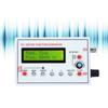
MODE: Mode key is used to switch the output waveform.
CURSOR: Used to move the cursor (use +- key to adjust the frequency).
RUN/STOP: Run or stop the waveform output.
When the cursor is not blinking, the waveform will be output, and other keys are invalid.
+: Frequency +
- : Frequency -
DCOFFSET: DC bias switch
Press ON to adjust the yellow knob to adjust the DC component of the signal.
Pop up to OFF, the DC component of the signal is 0.
FILTER: Filter switch, when the signal is close to 300K or more sine wave, press this button, the waveform will become
clean. But the signal amplitude will also become smaller
AMP: Side button to adjust the signal amplitude (clockwise amplitude becomes larger)
V. Use steps .
1.take out the matching USB to 3.5MM line inserted into the power input port (power can choose a computer USB
interface or cell phone charging head or charging treasure, it is recommended to choose through the 3C certification of the
power supply, poor power supply will make the signal generator does not work properly)
Access to the BNC to clip line, red clip access to the oscilloscope probe, black clip and oscilloscope GND clip connected.
2. press the power switch, press the MODE key to select the waveform to be output
SIN: Sine waveform
Lorenz: Lorenz pulse
Square: Square waveform
Gaussian: Gaussian pulse
Triangle: Triangle waveform
Sinc: Sinc pulse
Sawtooth: forward sawtooth wave
Half-wave: Half-wave
Resawtooth: Anti-sawtooth waveform
Full-wave: Full wave
ECG: Electrocardiogram
Schumann: Schumann wave
EXP-rise: Exponential rise
Noise: Noise wave
EXP-decay: exponential decrease
3.Adjust the frequency
Press the CURSOR key to move the cursor, with the + - key to adjust the frequency you want to output, and then pressthe RUN/STOP key to turn on the signal generator (here the cursor
does not blink) DDS oUT terminal will have the
corresponding signal output!
Adjust the frequency in steps of 0.01 HZ.There are two modes of adjustment
ADC-DEC MODE1: Adjust the current cursor value bit, participate in rounding and debit.
ADC-DEC MODE2: Adjust the current cursor numeric value bit, do not participate in rounding up or down.Turn off the power, press and hold the MODE key, press the powe
switch, and release the MODE key after about 10
seconds The screen displays ADD-DEC MODE2 Explanation of adjusting to ADD-DEC MODE2 mode.
Repeat the above steps to switch back to ADD-DEC MODE1.
After setting, the parameters will be saved, so there is no need to set them again next time.
4.Adjusting DC Bias
lf you want to output a waveform with a center point of 0 and symmetrical positive and negative, you need to pop upthe DC OFFSET button.
VI.Adjust the waveform amplitude
Adjust the side amplitude AMP knob, clockwise increase, counterclockwise decrease (adjusted to the waveform is notdistorted)
VlI.Transmit signals using Schumann wave antennas
1.Plug in the power supply and press the POWER switch.
2.Press MODE to adjust the waveform to Wave:Schumann.
3.Turn off the DC OFFSET switch
4.Adjust the side AMP amplitude knob (to the center position)
DIY Supplies: Electrical
High-concerned chemical: None
Advantage: Signal generator,functions generator,signal generator, FG-200 dds,laboratory function generator,rf generator,audio frequency generator,xr2206 function signal generator,Generator,frequency generator,frequency inhibitor,dds,electric generator
Semi-finishedproduct: Yes
Display Size: 3.0 - 4.9 Inches
Origin: Mainland China
Battery Included: no
Brand Name: GlintDeer
Certification: CE


 Возврат по недоставке