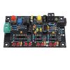
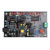
Quantity : 1
High-concerned chemical : none
Package : TQFP
is_d : Yes
Supply Voltage : As Description
Application : Speaker
Type : Module
Brand Name : DIY NOW
Origin : Mainland China
Condition : New
Condition : New
Type : T2 Amplifier OP AMP Tester
Key Word : AMP Tester
Dropship : Support
T2 Amplifier OP AMP Tester For Single Mono Dual Quad OPAMP Chip High Speed Low Differentiation Tester Board Electronic Kit
Feature:
1. Supports testing of single, dual, and quad op amps, offering a wide range of applications.
2. Capable of measuring parameters such as slew rate, quiescent current, and DC offset.
3. Clear distinction between high-speed and low-speed op amps, ensuring performance at a glance.
4. Provides testing of high-frequency 200kHz and low-frequency 10Hz square wave signals.
5. Equipped with test terminals for measuring quiescent current under ±5V power supply conditions.
Product Description:
This upgraded version of the T2 operational amplifier test board can be used to test common single, dual, and quad op amp chips, as well as finished boards. This board can determine whether an IC is suitable for amplification and also assess its slew rate, helping to identify low-speed chips masquerading as high-speed ones.
Product Parameters:
Power Supply Requirements (Two Modes):
1. Wire Connection: Voltage: DC 12V, Current 100mA or higher.
2. Use a standard monitoring power supply: a 12V/1A power adapter with a 5.5*2.5mm plug (positive inside and negative outside). (You can choose any one based on your needs.)
Single op amp models: LM741, LF356, NE5534, TL071, TL081, 0P07, and other standard packaged single op amps.
Dual op amp models: LM358, NE5532, TL072, TL082, MC1458, RC4558, 0P275, AD827, and other standard packaged dual op amps.
Quad op amp models: LM324, TL074, TL084, LF347, AD713, and others.
PCB size: 95.5 x 57.5 mm
Product List:
1 x module
Test Principle:
The signal source generates a high-frequency square wave of 200 kHz and a low-frequency square wave of approximately 10 Hz. The op amp under test is connected to a buffer circuit. High-speed op amps operate normally when inputting high- and low-frequency square wave signals, as evidenced by the corresponding red LED lighting up (200kHz) or flashing (10Hz) in sync with the yellow LED.
Low-speed op amps, when inputting high-frequency square wave signals, fail to fully output the waveform, resulting in the corresponding red LEDs lighting up, either one or both. Only when inputting low-frequency signals do they output normally, with the corresponding red LED flashing in sync with the yellow LED.
Test terminals are provided on the board to test the quiescent current of the op amp under ±5V power supply conditions. The quiescent current can also reveal some characteristics of the op amp and can also be used to distinguish models.
There are three testing methods:
1. Quiescent current with the chip connected as a buffer.
2. High-frequency signal operation.
3. Low-frequency signal operation.
4. Output DC voltage with the chip connected as a buffer, input grounded.
Some usage tips:
1. Can be used as a converter board for 5.5-inch power supplies and wire connections. The terminal blocks on the board are connected in parallel with the 5.5" DC power jack, allowing them to be used as a wire bridge.
2. Connect a wire to the output terminal to use as a square wave signal source with a frequency range of 20Hz-200kHz.
Testing Notes:
1. Only one chip can be tested at a time. Only one of the three test sockets can be used.
2. TP1 test terminal is used to test the quiescent current of the op amp. Use the DC voltage setting of a digital multimeter. The test terminal is a 10Ω resistor. The voltage across the resistor is I = V/10 (mA). For example, if V = 15mV, the quiescent current is I = 1.5mA. (In this case, there's no need to press the red switch on the right in the image.)
3. TP2 test terminal can be used with a multimeter in the DC voltage setting to test the DC offset voltage of the op amp output.
4. For SMD packaged op amps, try using a converter clip.
label:yes


 Возврат по недоставке