High-concerned chemical : none
Type : Module
Brand Name : diymore
Origin : Mainland China
Condition : New
Features:
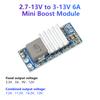
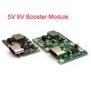
1. DC-DC boost power module, with a wide input voltage range (5-15V) and an optional fixed output voltage.
2. The maximum output current reaches 5A, supporting high-power applications with high efficiency and low heat generation.
3. Operating frequency of 350KHz, standby current less than 1mA, stable and reliable performance.
4. Built in multiple protection mechanisms to prevent abnormal situations such as overload and short circuit.
5. The module is compact in size and can be used for wire bonding or PCB mounting.
Parameter:
Type: DC-DC boost power module
Input voltage: 5-15V [Description: The input voltage should be 1V lower than the output voltage (the minimum input voltage is 2.7V to start the chip, and the output will stop when discharged to 2.2V, it is recommended to have an input voltage of 5V or above). The smaller the input and output voltage difference, the lower the heat generation and the higher the efficiency. 】
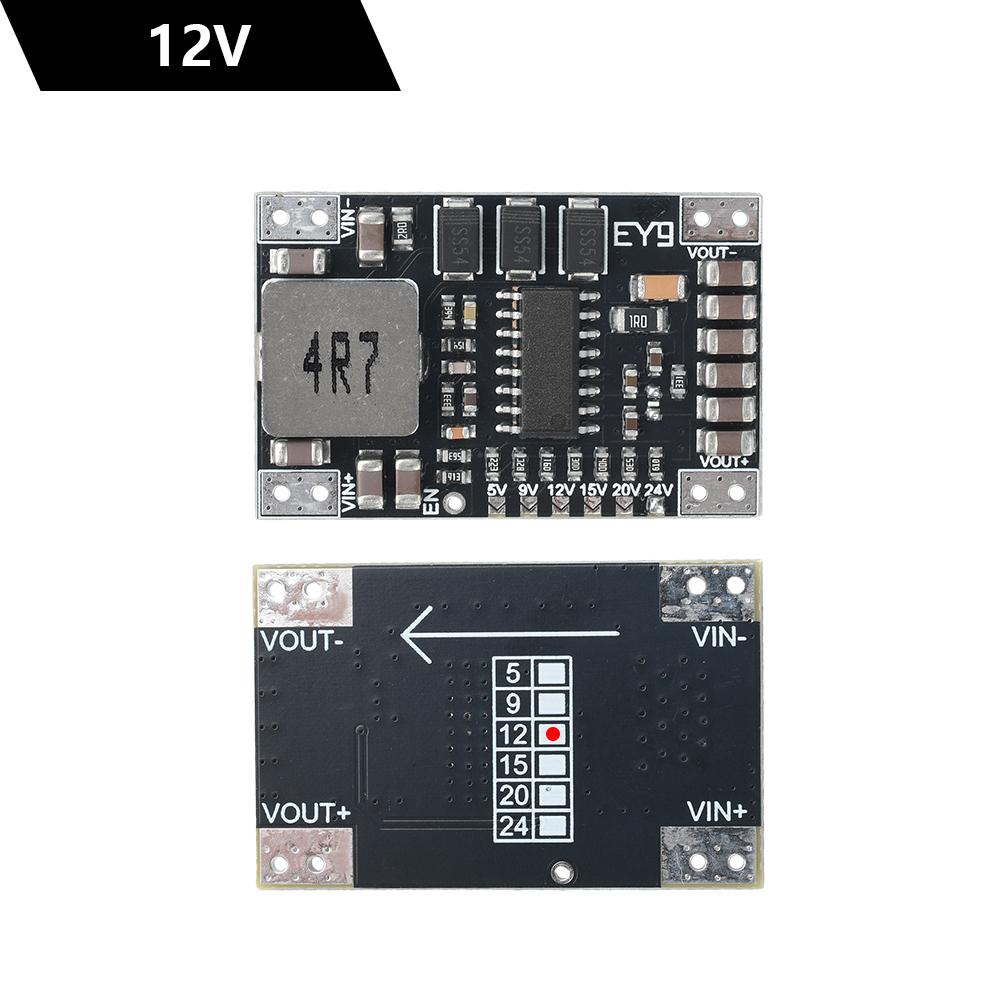
Output voltage: 5V/9V/12V/15V/20V/24V optional fixed voltage output [Note: Short contacts must be disconnected cleanly, if not short circuited, the chip will be burned. It is recommended not to change the output voltage by yourself]
Output current: Maximum 5A [The maximum current depends on the input voltage and current. The maximum input current is 6.5A. For example, if the input is 5V and the output is 12V, with a current of 6A, 6A * 5V=30W30 ÷ 12V=2.5A current (plus losses) (the voltage difference between the input and output should not be too large, as it affects efficiency)
Method for calculating output power:
Output current=(input voltage x 6) ÷ output voltage
Output power=output current X output voltage
Working frequency: 350KHZ
Standby current:<1MA
Installation method: wire bonding, surface mount
Size: 35 length * 22.1 width * 5.5 height MM
Module description and usage precautions
1.The spacing between the dual holes of the module is 2.54MM
2. Can be attached to PCB board for use
3. The negative pole of the module is grounded, and the input terminal should not be connected to the opposite positive and negative poles. Connecting them in the opposite direction will cause overheating.
5. The module soldering wire should be reliable, the wire should be short and thick, do not twist the wire, ensure that it can withstand excessive current, and be careful not to touch other components (which may burn the chip) during soldering
6. It is recommended to use a 470UF/25V electrolytic capacitor in parallel at the input end of the module for a long time (near the module), and a 100UF or 220UF/25V electrolytic capacitor in parallel at the output end
7. This module is not suitable for inductive loads such as motors, relays, and speakers. Reverse voltage will break down the chip, and the principle of reverse electromotive force of the motor can be found online. Here is just a solution provided: a TVS tube or diode needs to be connected in parallel at the output end. Try to choose a large package (TVS tube has a life) (bidirectional TVS tube, the voltage of TVS tube is 2 volts higher than the output voltage, a little larger is also acceptable)+electrolytic capacitor 100UF or 220UF is used in parallel.
Package Includet:
1X module
label:yes




 Возврат по недоставке