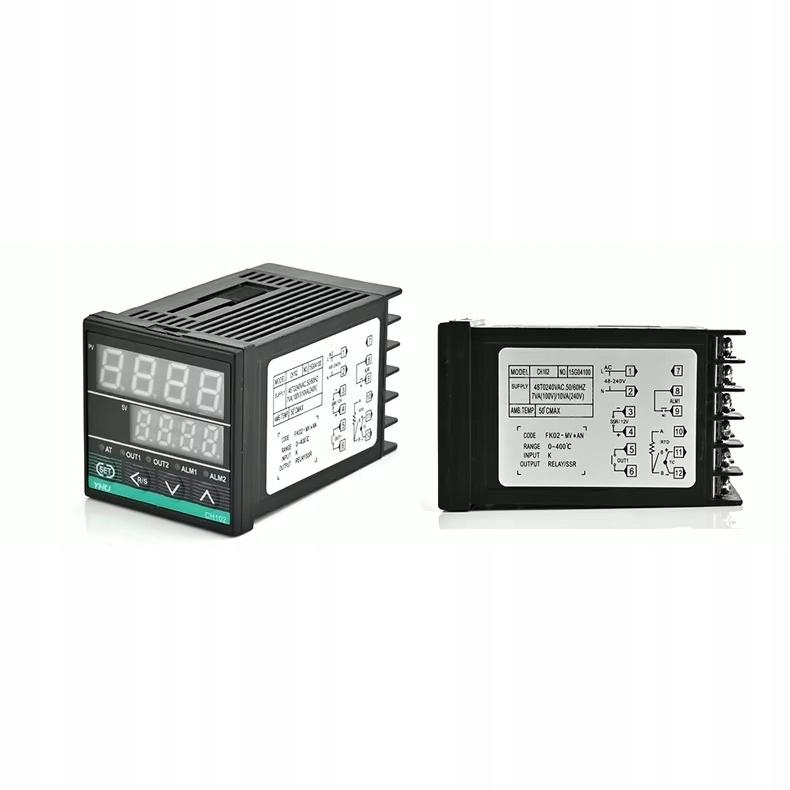
CH102FK02-MV*AN – PID Temperature Controller | 48x48 mm | SSR 12VDC + 10A relay | -199.9~1800°C | PT100, K, J, R, S | Auto-tuning | LED | Wide temperature range: Supports -199.9 to 1800°C depending on the connected sensor. Multi-probe compatibility: Thermocouples K, J, R, S, B, E, T and RTD PT100 and Cu50. Two independent control outputs: 10A/2300W relay + 12VDC SSR output – flexible control of heaters and SSR. Temperature alarm: AL1 (NO) output with LED indication – quick response to exceeding the set value. Compact design: Only 70 mm depth – ideal for shallow cabinets and enclosures. LED display: Dual screen – PV (red), SV (green) – ensures quick and clear reading. Easy setup: REX C100 style menu – easily change settings such as temperature range, probe type, PID/ON-OFF. Easy mounting: 45x45 mm mounting hole, rear clip mounting – hassle-free installation. PID autotuning: AT function – automatic adjustment of parameters to operating conditions. Specification: Model: CH102FK02-MV*AN Power supply: 110–240V AC, 50/60Hz SSR output: 12V DC / 21mA (SSR relay control) Relay output: 10A / 230V (resistive) Alarm output AL1: 230V AC / 3A (NO) Measurement accuracy: ±0.5% or ±3°C Sampling cycle: 0.5 s Temperature range: -199.9 to 1800°C Supported sensors: K, J, R, S, B, E, T, PT100, Cu50 Operating mode: Heating / Cooling PID autotuning: Yes (AT function) Hysteresis, proportionality, integral, derivative time – configurable Display: 2x LED (PV and SV) Housing dimensions: 48 x 48 x 70 mm Mounting hole dimensions: 45 x 45 mm Operating temperature: 0–50°C Humidity: 0–90% RH (no condensation) Instructions for connecting the CH102FK02-MV*AN temperature controller (according to the diagram): Controller power supply (110–240V AC): Pin 1 – L (phase wire) Pin 2 – N (neutral wire) SSR control output (12VDC): Pin 3 (-) – Minus of SSR relay power supply Pin 4 (+) – Plus of SSR relay power supply Connection to SSR relay control input (e.g. FOTEK SSR 12VDC) Relay output OUT1 – 10A (to contactor, heater or other receiver): Pin 5 – phase output from the relay Pin 6 – neutral/ground – connected to contactor or receiver Alarm output ALM1 – 230V / 3A (Normally Open): Pin 8 and 9 – connected to an alarm device (e.g. lamp, buzzer) Activates after exceeding the set temperature (SV) Connection of K-type temperature sensor (thermocouple): Pin 11 (+) – red wire of thermocouple Pin 12 (-) – blue wire of thermocouple Connection of PT100-type temperature sensor (RTD – 2 wires): Pin 10 (A) – wire 1 Pin 12 (B) – wire 2 Note: For PT100, make a jumper between pins 11 and 12 Mounting: Make a mounting hole 45 x 45 mm Insert the regulator from the front From the back, put on and press the mounting clips – ready! Installation notes: When using an SSR relay, use a DC-AC SSR (e.g. 10A, 25A, 40A – depending on the receiver power) SSR outputs (pin 3 and 4) are used to directly control the SSR with 12VDC voltage The relay output (pin 5 and 6) supports receivers up to 2300W (max. 10A) The alarm power supply (ALM1) requires its own voltage source (e.g. from the same 230V mains) IMPORTANT: Make sure that the sensor is correctly selected for the input type (TC/PT100) For temperatures >400°C or a change of the probe type – change the factory settings SL1 and SLH Installation in accordance with safety standards – maintain insulation distances



 Товар из Польши


 Возврат по недоставке