Reversed polarity makes the module not damaged by the wrong connection of power supply.
Automatic power saving function, the module will not consume much power.
Lower trigger relay, widely application for power control.
Description:
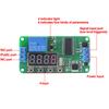
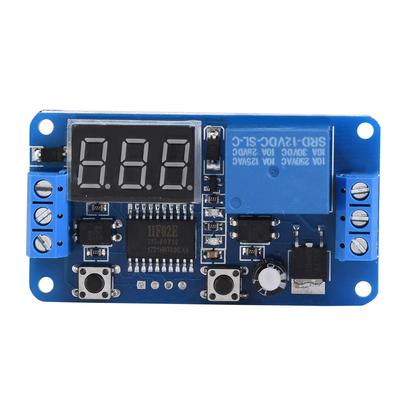
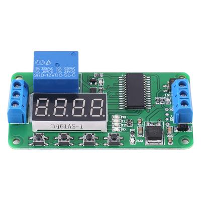
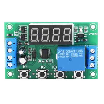
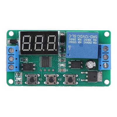
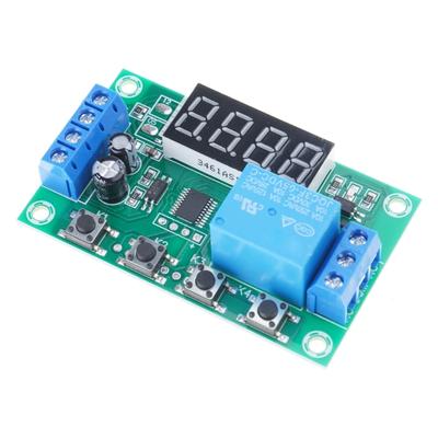
This multifunction relay control module adopted military grade double-sided PCB board, for using. There are 18 kind of functions you can choose. All the setting options can be saved automatically, your can no longer worry about losing the data.
Features:
Reversed polarity makes the module not damaged by the wrong connection of power supply.
Automatic power saving function, the module will not consume much power.
Lower trigger relay, widely application for power control.
High voltage resistance module has the stable performance for using.
All the setting options can be saved automatically, not easy to lose the content.
Specifications:
current: voltage: 12V
temperature: -20 celsius .60 celsius
. load ability:
0-30VCelsius10A, AC 0-250VCelsius10A(normally open end)
0-28VCelsius10A, AC 0-125VCelsius10A(normally close end)
Size: Approx. 7.6 x 4cm Celsius 2.9 x 1.5inch
Weight: 31g
Note: Please contact us for instruction.
Function 1:
Timing Pull-in: after power on, when arrived the setting time T 1, the relay pull-in, and the T 1 can be between 0.1 second - 270 hours,
give IN1 interface a low pulse signal, repeat the function.
Function 2:
Timing Disconnect: after power on the relay pull-in, when arrived the setting time T 1, the relay disconnect, and the T 1 can be between 0.1 second - 270 hours,
give IN1 interface a low pulse signal, repeat the function.
Function 3:
Timing Pull-in Then Disconnect: after power on, the relay do not pull-in, when arrived the setting time T 1 relay pull-in; when arrived the setting time T 2 relay disconnect, and the T 1 and T 2 can be between 0.1 second - 270 hours, give IN1 interface a low pulse signal, repeat the function.
Function 4:
Timing Disconnect Then Pull-in: after power on, the relay immediately pull-in, when arrived the setting time T 1 relay disconnect; when arrived the setting time T 2 relay pull-in, and the T1 and T 2 can be between 0.1 second - 270 hours, give IN1 interface a low pulse signal, repeat the function.
Function 5:
Unlimited Cycle Timing Mode A: after power on, the relay don t pull-in, when arrived the setting time T1 relay pull-in; when arrived the setting time T 2 relay disconnect, then repeat the status, and the T1 and T 2 can be between 0.1 second - 270 hours, give IN1 interface a low pulse signal, repeat the function.
Function 6:
Unlimited Cycle Timing Mode B: after power on, the relay immediately pull-in, when arrived the setting time T1 relay disconnect; when arrived the setting time T 2 relay pull-in, then repeat the status, and the T1 and T 2 can be between 0.1 second - 270 hours, give IN1 interface a low pulse signal, repeat the function.
Function 7:
Limited Cycle Timing Mode A: after power on, the relay do not pull-in, when arrived the setting time T1 relay pull-in; when arrived the setting time T 2 relay disconnect, then repeat the status NX times, the T1 and T 2 can be between 0.1 second - 9 seconds, the cycle times NX can be between 1- 9, give IN1 interface a low pulse signal, repeat the function.
Function 8:
Limited Cycle Timing Mode B: after power on, the relay immediately pull-in, when arrived the setting time T1 relay disconnect; when arrived the setting time T 2 relay pull-in, then repeat the status NX times, the T1 and T 2 can be between 0.1 second - 9 seconds, the cycle times NX can be between 1- 9, give IN1 interface a low pulse signal, repeat the function.
Function 9:
Self-locking Mode: give IN1 interface a low pulse signal, the relay pull-