Type : Voltage Regulator
Origin : China
Condition : New
PinPin
Function
ESP-8266 Pin
TX
TXD
TXD
RX
RXD
RXD
A0
Analog input, max 3.3V input
A0
D0
IO
GPIO16
D1
IO, SCL
GPIO5
D2
IO, SDA
GPIO4
D3
IO, 10k Pull-up
GPIO0
D4
IO, 10k Pull-up, BUILTIN_LED
GPIO2
D5
IO, SCK
GPIO14
D6
IO, MISO
GPIO12
D7
IO, MOSI
GPIO13
D8
IO, 10k Pull-down, SS
GPIO15
G
Ground
GND
5V
5V
-
3V3
3.3V
3.3V
RST
Reset
RST
All IO have interrupt/pwm/I2C/one-wire supported(except D0)
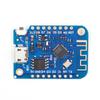
ProgrammingThe D1 mini has a micro USB for auto programming.
Also you can programming it using OTA.
WarningsAll IO is work at 3.3V.
Installing Hardware packageThere is two ways to install hardware package, Boards Manager and git.
Installing with Boards ManagerStarting with 1.6.4, Arduin allows installation of third-party platform packages using Boards Manager. We have packages available for Windows, Mac OS, and Linux (32 and 64 bit).
Upload Using:
Serial - Use USB port on board to upload flash
OTA - Use OTA to upload flash
CPU Frequency:
80MHz
160MHz
Flash Size:
4M (3M SPIFFS) - 3M File system size
4M (1M SPIFFS) - 1M File system size
Upload Speed:
921600 bps - recommend
Installing Examples
Simple Way
· Download Examples files form here.
· Rename the uncompressed directory to D1_mini_Examples
· Move directory to Sketchbook_directory
· The path will look like Sketchbook_directory/D1_mini_Examples
· Restart the Arduin IDE
· All examples are under File→Sketchbook→D1_mini_Examples
Git Way (Recommend)
We recommend using git to install Examples, you can always get the latest version of it.
· Clone repository into Sketchbook_directory directory (or clone it elsewhere and create a symlink).
cd Sketchbook_directory
Features: 1. Based on ESP-8266EX 2.Arduin compatible, using the Arduin IDE for programming 3.11XI / O pin 4.1XADC pin (input 0-3.3V) 5. Support OTA on line 6. Onboard 5V 1A switching power supply (maximum input 24V)
The line layout is compact and regular, with good electrical insulation and mechanical stability, and can maintain stable performance under different temperature and humidity environments to ensure accuracy and reliability.
In circuit design, carefully planned lines are like precision transportation networks, and lines of different widths and spacings undertake different currents and signals transmission tasks respectively. The key signal lines are impedance matching processing, which greatly reduces signal reflection and attenuation and ensures the stable transmission of high-frequency signals.
All kinds of electronic components are soldered on the circuit board, and the solder joints are full, round, and firm and reliable. Core components like chips are perfectly connected to the circuit board through fine packaging processes to achieve high-speed data processing and interaction.
This circuit board has a wide range of responses in many fields. Whether in the industrial control field that requires extremely high stability or consumer electronics field that pursues extreme performance, it can provide solid guarantees for the stable operation of the equipment with its excellent design and reliable performance, and help various electronic devices play a powerful role.